GPIO Port
(X-Series)
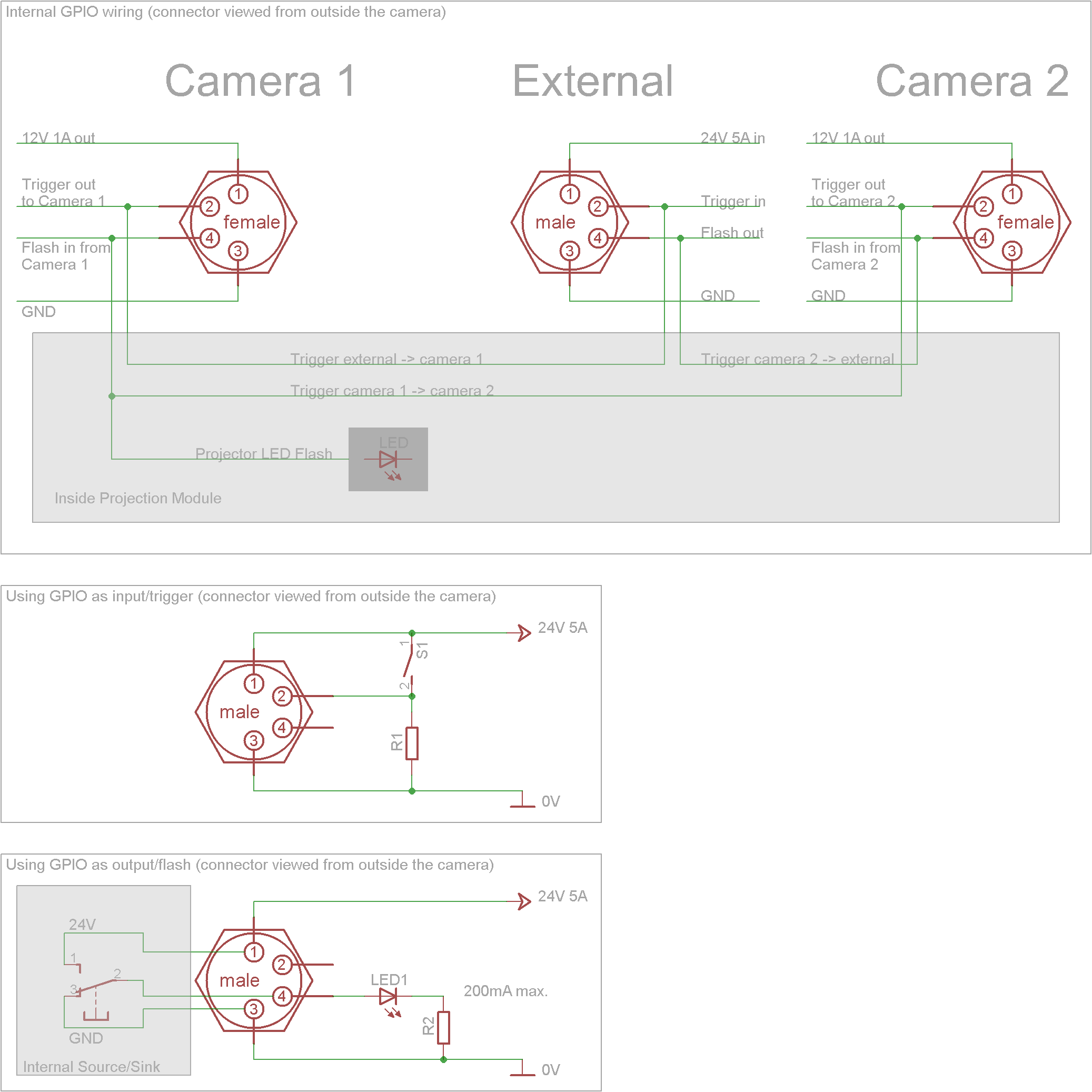
The GPIO ports use 4 pin M8 sensor/actuator connectors. One male connector for external power supply and synchronization, and two female connectors for power supply and synchronization of camera 1 and 2.
Pin Assignment ‘External’
1 |
Power Supply Input 24V DC, 5A |
2 |
Digital Input, Trigger, 0V / 24V |
3 |
Ground (GND) |
4 |
Digital Output, Flash, 0V / 24V |
Note
The trigger and flash signals are ground referenced and push-pull driven.
Electrical Characteristics ‘External’
Digital Input
Switching threshold low -> high ~7.1V
Switching threshold high -> low ~6.2V
Resistance ~11kOhm
Digital Output
Voltage level low < 0.7V
Voltage level high > DC_in - 0.7V
Maximum curent (source/sink) 30mA
Pin Assignment ‘Camera1/2’
1 |
Power Supply Output 12V DC, 1A |
2 |
Digital Output, Trigger Signal for Camera1/2, 0-12V |
3 |
Ground (GND) |
4 |
Digital Input, Flash Signal from Camera1/2, 0-12V |
GPIO Wiring and Usage

Output Drivers
On the ‘External’ GPIO port the source and sink output drivers can be enabled separately for safe interoperability with other equipment. The output drivers are both disabled by default, thus before using the external flash output signal you need to enable at least one output driver in the IO/Output/Drivers node.
In order to use X-series cameras with our simple M8-3pin. cabling you should only enable the Source driver as in all other N-series M8 cables the cameras flash outputs are connected to only drive the signal pin high. This will ensure that even when multiple cameras output a flash signal no short circuit situation can happen on the signal pin.
If you use the X-series external flash output with other equipment you will likely want to enable both drivers in order to generate steep rising and falling edge signals.
Note
The connection diagram for internal trigger signals at the top of this page is intentionally simplified. All internally forwarded trigger signals are digitized and then output again with push/pull drivers.
